An Overview of UML
What is It?
UML, also known as The UML is a graphical modeling language that helps people design, describe, and discuss software systems.
Prior to the introduction of the UML (in 1997) there were tons of software development methods out in the world, each using their own modeling languages, including: Booch, OMT (Rumbaugh), OOSE (Jacobson), Fusion (HP), OOA/OOD (Coad/Yourdon), Recursive Design (Shlaer/Mellor), CRC (Beck/Cunningham), Responsibility Driven Design (Wirfs-Brock), and Odell. The "three amigos" Booch, Rumbaugh and Jacobson decided to put together the best parts of their work, and add other stuff, to make UML. The 'U' stands for "Unified".
The UML is still evolving. It has gone through several versions (the complete list of versions is maintained at the OMG site); some milestones are listed here:
- Version 1.3: March 2000
- Version 1.5: March 2003
- Version 2.0: July 2005
- Version 2.2: February 2009
- Version 2.3: May 2010
- Version 2.4.1: Augut 2011
What is it for?
UML can model just about any kind of computing system. The system is modeled with a collection of diagrams. Each diagram represents some aspect of some part of the system. You choose how many diagrams you want to make, and even the level of detail of the diagram. The diagrams are really there to help you talk about your system with others.
UML can help you in:
- Forward Engineering: Sketch out, or design your system, before you code it.
- Reverse Engineering: Generate pictures of existing code to help you better understand it.
Fowler's three modes of using the UML
- Sketching (by far the most common)
- Blueprinting
- Programming
The latter two require sophisticated tools. Be careful with them. Blueprinting shouldn't go "all the way down to statements of code." Skecthes are fine: even if they are informal, they are still useful.
Diagram Types
Formally the UML defines a graphical notation and a meta-model. The notation is what most users care most about, and the most visible part of the notation is the collection of 13 diagram types.
- Diagram
- Structure Diagram
- Class Diagram (shows the static, structural, model elements, mainly classes and types)
- Composite Structure Diagram (shows the internal structure and interaction points of a class or component or use case)
- Object Diagram (shows objects and their relationships at a point in time)
- Package Diagram (shows the grouping of model elements into packages and the releationships between packages)
- Component Diagram (shows components — e.g., source code, binaries, media — and their dependencies)
- Deployment Diagram (shows the configuration of processing devices and which components run on them)
- Behavior Diagram
- Use Case Diagram (shows actors and use cases)
- Activity Diagram (shows processes)
- State Machine Diagram (shows behavior in terms of state transitions)
- Interaction Diagram
- Sequence Diagram (shows an interaction by laying out objects across the top and running their lifelines down the diagram, wit messages exchanged between lifelines to make the sequence of messages clear)
- Communication Diagram (shows an interaction where the layout of objects is arbitrary and the sequence of messages is shown by numbering them)
- Interaction Overview Diagram (groups interaction diagrams into a high level activity diagram)
- Timing Diagram (shows state changes over time)
- Structure Diagram
For an explanation of the UML diagram types with detailed examples, you can see:
- Martin Fowler's UML Distilled
- UML Reference Guide
- Scott Ambler's UML Pages
- The Wikipedia article on UML
- OMG's UML Site
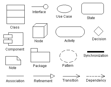
Diagram Elements
Some of the graphical constructs from which diagrams are made are:
- Icon: graphical symbol of fixed size and shape (doesn't hold contents)
- Two-dimensional symbols: have variable size and can expand to hold contents, may be divided into compartments
- Paths: seqences of line segments with attached endpoints. The endpoints are always symbols (no dangling paths). May also have icons at the end to qualify the meaning of the path symbol.
- Strings: text
- Name: A string that uniquely identifies some model element within some scope
- Label: A string attached to a graphic symbol
- Keyword: Text enclosed within "«" and "»" to convey some concept. There are many keywords so we don't need zillions of specialized graphical symbols.
- Expression: A linguistic formula that yields a value
- Some model elements:
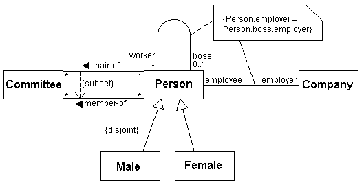
Types vs. Instances
A type is like a generic descriptor for a concept and an instance is an item described by a type. Where possible, UML indicates this distinction by underlining the name for instances. Examples:
- Class vs. Object
- Association vs. Link
- Node vs. Node instance
- Parameter vs. Value
- Operation vs. Call
- Use case vs. Scenario
Extension Mechanisms
Comment
Arbitrary descriptive text within a note symbol. The note symbol is attached to another model element with a dashed line. The comment is not "executable" but should mean something to a reader.
Constraint
Semantic relationship among model elements that must hold for the model to be valid. Shown as a text string in braces
Property
A property is any value attached to a model element. These values are generally non-visual. Some properties are predefined but users can invent their own. Examples
{author="Joe" deadline="1998-11-26" status=draft}
{abstract} same as {abstract=true}
Stereotype
A new class of modeling element introduced at modeling time: a subclass of an existing modeling element with the same form but a specific new intent (a usage distinction). Shown as a keyword (enclosed within "«" and "»") and appears above or to the left of the name of the modeling element being described. Can also appear in a list in which case it describes what follows.
You can invent new icons for stereotypes and collapse the elements (with the usual warning that inventing too many special icons may impede readability and portability).
![]()